This is a future validation protocol: survey polygon, grid, altitude, speed, overlap, takeoff, safe completion, geofence/rally, protocol upload and read-back comparison. At this stage, execution is permitted only in a simulator/SITL.
KairOS has not passed autonomous-mission validation; real Auto execution is neither claimed nor authorized by this page.
KairOS repository ↗On this page +
The guide’s goal and its honest boundary
The workflow covers automated survey: polygon → grid → parameters → validation → upload → Auto execution → logs. The planner can work offline without an FC; until separate flight validation, upload and execution take place only in a simulator/SITL.
What must be ready before planning execution
- Mission Control is running and connects to the FC; the offline planner can be opened beforehand.
- GPS 3D Fix and 8+ satellites before upload/execution.
- ArduPilot, PX4 or iNav; MAVLink missions for ArduPilot/PX4, MSP path for iNav.
- Battery at least 80% before takeoff.
- An open, authorized outdoor area with sufficient clearance around the polygon.
- Verified Home, altitude frame, RTL altitude, geofence action and mode switch.
- Weather and wind within the limits of the vehicle, payload and plan.
Polygon, grid settings and detailed checks
1. Open Plan
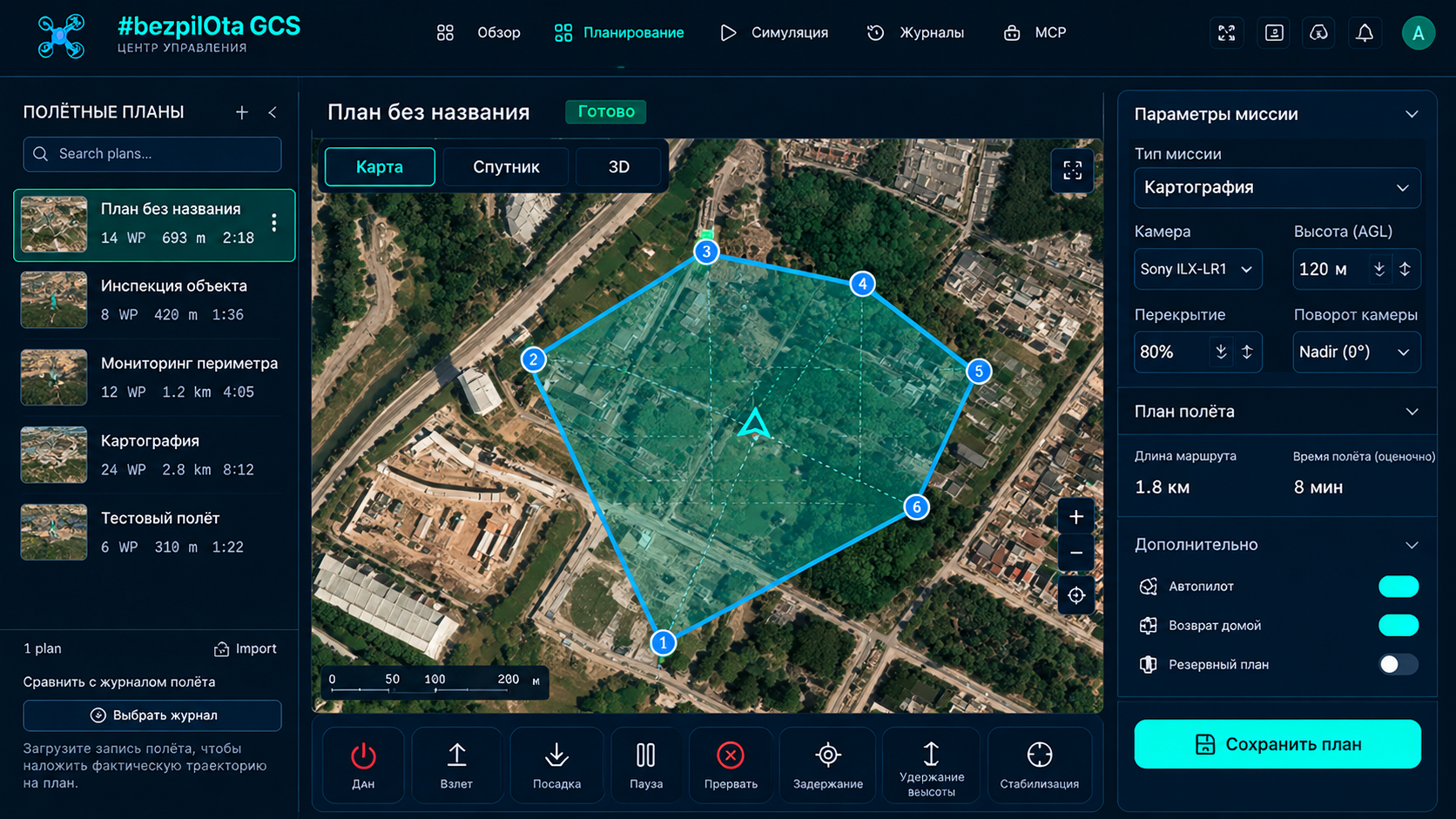
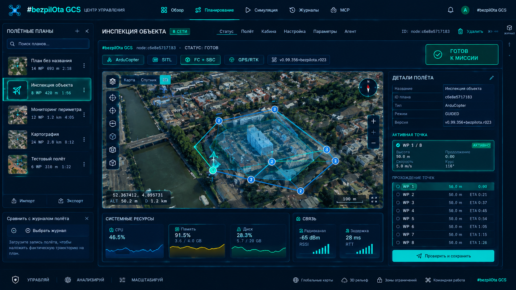
Open the Plan tab. The map shows the current GPS position when an FC is connected, or the default area; the left panel contains the waypoint list, pattern generators, settings and import/export.
2. Define survey area
Draw a polygon or import KML, GeoJSON or CSV. For edge coverage, extend the boundary slightly beyond the actual site while preserving a safe buffer.
3. Generate Survey Grid
Set altitude, speed, front/side overlap, angle and camera trigger. Auto-optimize may reduce the number of turns.
4. Inspect plan
Check total waypoints, distance, time, legs, photo count and each item: sequence, coordinates, altitude and command.
| Setting | Target starting point | Effect |
|---|---|---|
| Altitude | 50 m general; 30 m detail | GSD, coverage, obstacles, legal limit |
| Speed | 5–8 m/s | Motion blur, mission time, wind margin |
| Front overlap | 75% | Along-track stitching |
| Side overlap | 65% | Cross-track stitching |
| Grid angle | 0° or auto-optimize | Turns, wind exposure, line direction |
| Camera trigger | Distance or time | Photo spacing |
Add an explicit start and safe ending
1. TAKEOFF to 50 m
2–N. Survey waypoints (NAV_WAYPOINT + camera triggers)
N+1. RTL (return to launch and land)
The takeoff item defines the climb before entering the grid. The last item must not leave behavior undefined; RTL returns to Home and performs the configured landing. At a particular site, landing at the current location or another ending may be safer—decide in advance, not after a low-battery warning.
Geofences and rally points as separate safety layers
Geofence
Recommended buffer of 50–100 m around the work area, example maximum altitude of 100 m and RTL breach action. Check FENCE_ENABLE, FENCE_TYPE and FENCE_ACTION for ArduPilot.
Rally points
Preselected safe landing points with approach altitudes for cases where Home is unavailable or the return path is unsafe.
Validate before upload
- Missing takeoff or undefined final action.
- Waypoint outside the geofence.
- Altitude above the configured/legal limit or below obstacle/terrain clearance.
- Speed outside the vehicle/payload’s established range.
- Duplicate points or insufficient spacing.
- Incorrect sequence or a command incompatible with the firmware.
- A grid leg crossing a prohibited area or lacking a safe turning buffer.
Red errors must be corrected. Yellow advisories must be read and consciously accepted; they are not decorative warnings to dismiss. After any change to the polygon, altitude, speed, fence or ending action, run validation again.
Upload, ACK and mandatory read-back
Check FC online
Connection green, correct vehicle selected, parameters and current mission state available.
Upload Mission
The GCS sends MISSION_COUNT; the FC requests each MISSION_ITEM_INT; the GCS responds; the FC completes with MISSION_ACK.
Wait for ACK
The target response window is 1–5 seconds. Timeouts or NACKs remain errors; do not switch to Auto.
Download Mission
Download the mission from the FC and compare its exact item count, coordinates, altitudes and commands with the plan.
MISSION_COUNT
  → MISSION_REQUEST_INT
  → MISSION_ITEM_INT (message 73, integer lat/lon × 1e7)
  → MISSION_ACK
The target protocol accepts legacy MISSION_ITEM message 39 only for download compatibility; upload uses MISSION_ITEM_INT. MAVLink details remain standard and are not altered by the KairOS namespace.
Arm and hover before Auto
1. Final pre-flight
GPS, battery, PreArm, geofence, wind, Home, camera storage and link/failsafe.
2. Arm in Stabilize/Loiter
Do not arm directly in Auto for the first mission test.
3. Manual hover
Climb to 3–5 m and verify stability, control authority and telemetry.
4. Switch Auto
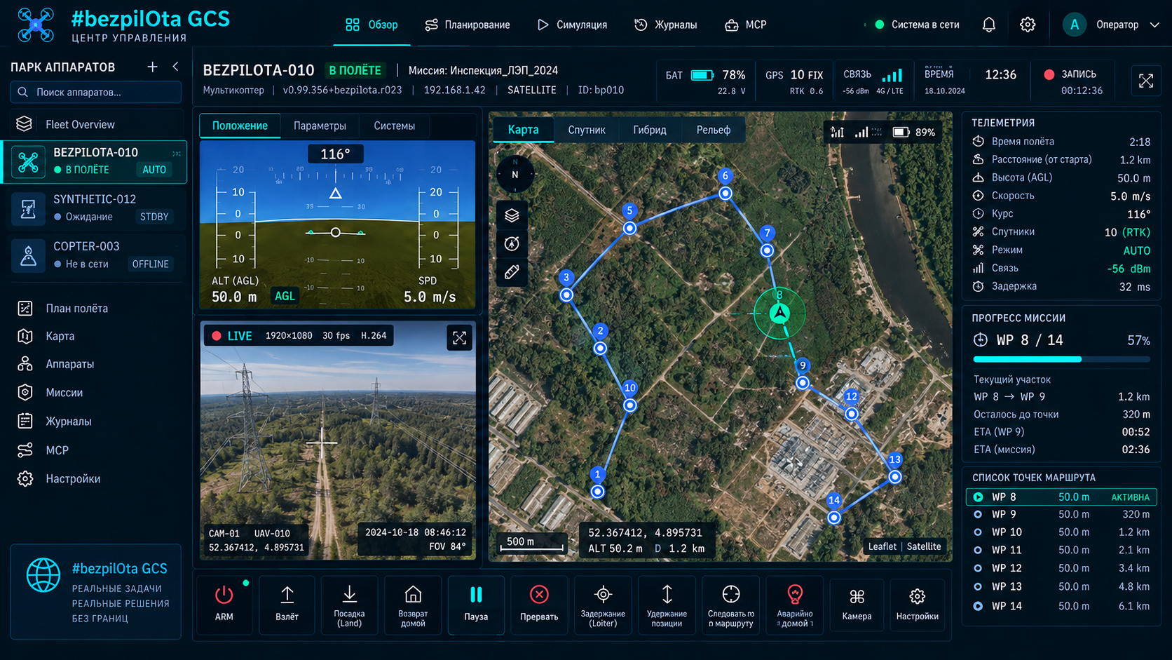
The FC climbs to takeoff altitude, flies to the first waypoint, completes grid legs/triggers, then performs RTL/landing.
5. Monitor
Monitor the current item, altitude, ground speed, battery, GPS/EKF, camera triggers and remaining time.
6. Land and disarm
After completion, verify touchdown, auto-disarm and saved logs.
Three ways to interrupt a mission and one last resort
| Action | Result | When |
|---|---|---|
| Loiter | Holds the current position/altitude | Pause to assess with healthy GPS/EKF |
| RTL | Returns to Home and performs the configured ending | The area/return path is safe and Home is correct |
| Land | Descends at the current location | The current location is safer than returning |
| Emergency Disarm | Immediately stops motors—the vehicle falls | An absolute last resort when continued thrust is more dangerous than falling |
Seven generators for different tasks
Survey Grid
Parallel lines with overlap for orthomosaics/mapping.
Orbit
A circle or arc around a point/structure with a specified radius and camera orientation.
Corridor Scan
Strips along a road, line, pipeline or another long object.
Expanding Square
A search square expanding from the starting point.
Sector Search
Radial legs from the center for systematic search.
Parallel Track
Parallel search lines with specified spacing.
Structure Scan
A path around a vertical object; requires specific obstacle and GNSS assessment.
Portable files and an optional cloud library
| Format | Purpose |
|---|---|
| QGC WPL 110 | Mission waypoints and commands |
| KML | Mission/boundary exchange with GIS tools |
| CSV | Tabular import/export |
| GeoJSON | Polygon boundaries and GIS geometry |
| Cloud mission library | Optional storage when the Convex backend is enabled |
When loading someone else’s file or an older file, recheck altitude frame, Home assumptions, firmware commands, fence, camera trigger and coordinates. A local-only deployment without Convex has no cloud library—this is normal.
Geometric preview and physics SITL are different checks
The Mission Control Simulation tab shows 3D terrain, path, camera trigger markers, timing, altitude profile and terrain warnings. This is a geometric preview: it does not model aerodynamics, wind, actuator limits, battery sag or estimator faults.
For physics/protocol validation, use SITL with the appropriate firmware version. After SITL, a controlled field test with reduced area, altitude and duration is still required.
Initial targets and battery margin
| Task | Target simulation altitude |
|---|---|
| Detailed capture | 25–30 m |
| General mapping | About 50 m |
| Overview | 80–100 m, only if legal and obstacle limits permit |
- Start with 75% front and 65% side overlap; if stitching is weak, side overlap can be increased to 70–75%.
- Orient the grid for the wind; choose lines that minimize unsafe crosswind turns.
- Plan to use no more than approximately 70% of the battery and retain a 30% reserve for wind, go-arounds and degradation.
- Check photo intervals against speed, exposure and camera write rate.
- Do not extend the polygon to the physical edge without safe turning and geofence buffers.